Continuing the creation of the engine-side bracket, I turned to that most reliable and inexpensive method of rapidly prototyping complex objects in three dimensions: CAD. That would be Cardboard Aided Design.
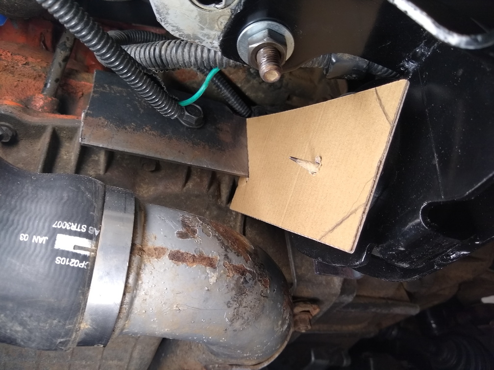
Starting with the left side, I made a slice of cardboard the same size as the bar stock that I’m working with and got it put in to place. Rather than trying to figure out what angle things needed to be held at to attach the connector, I left the bracket bolted to the engine, clamped the shaped bar stock to the body-side mount, and then tacked it in to place.
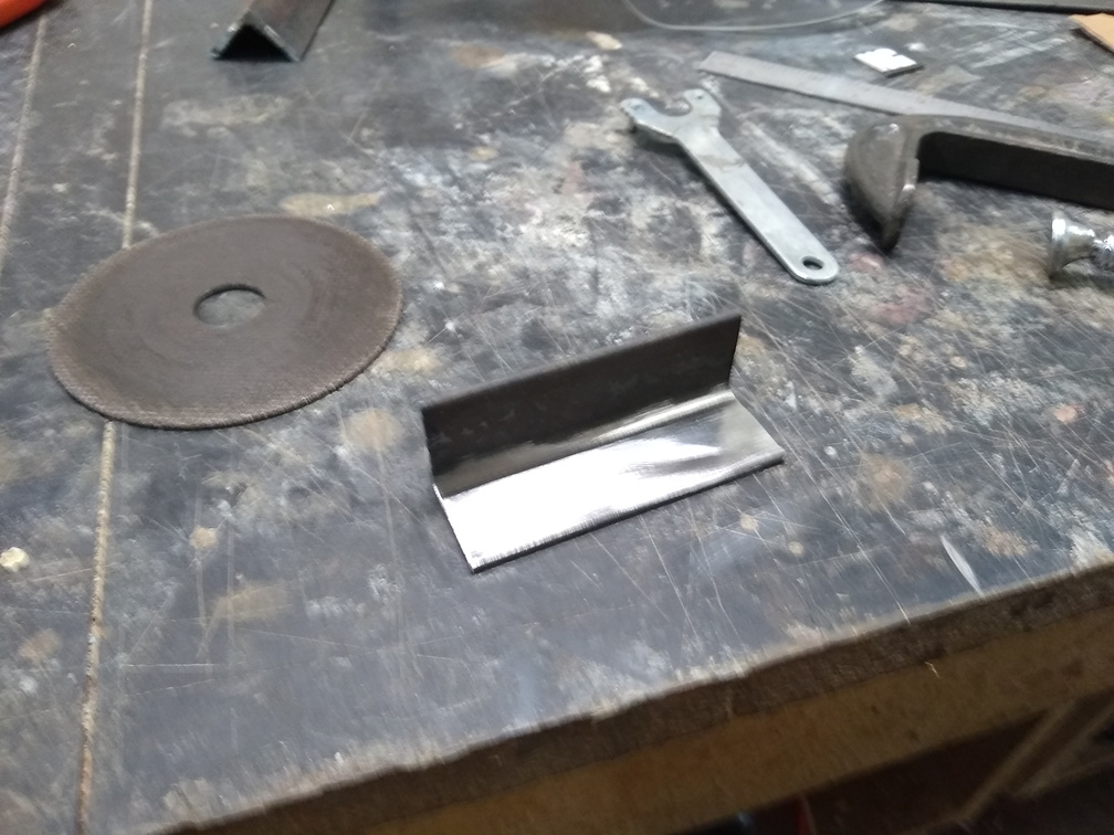
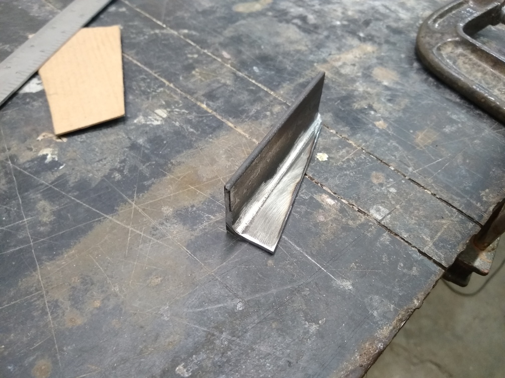
I did the same type of design on the right side, but there isn’t as much room to work with over there. In order to give that connector enough “meat” for a solid attachment, I cut down a bit of the angle to weld on to the existing bracket.
With the left side in place and the wedge added to the right side, the next step is to bolt the bracket back up, put the body-side mount in place, and make sure there’s enough room to slide the bar stock between the rubber mount and the wedge. Once that’s ground down to size, the bolt hole needs to be put into the left side, then the whole thing needs to be bolted up again so that the right side plate can be tacked on and the bolt hole location can be marked. Then the whole thing comes off again to weld up that plate, drill the bolt hole, and then bolt it all back up.
It will come off one more time because I need to put some gussets in place to give some strength to the bracket. Rather than applying those gussets right away, though, I need to ensure that I don’t block any bolt holes or constrict the space that the bracket needs to be attached to the body-side mount. So with the whole thing bolted up, I’ll go ahead and mark out the spots that I need to keep clear then pull the bracket off one last time to strengthen it, grind it down, paint it up, and then it should finally be good to go.
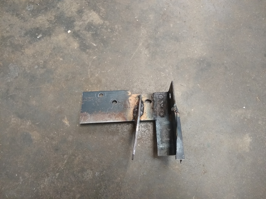
For now, here is the bracket in all its booger-weld glory: