Turdbo Neon

Project log for the re-building of the 1997 Dodge Neon Sport

Making the Connection Pt. 3

The bracket is getting much closer! The whole assembly got bolted back up to the car and the bracket was marked again. Not enough material had been removed from the bit of angle iron, so I ground that down some more. To make sure everything was held at the right angle, I put the body-side mount in place on the workbench, clamped the other plate on, and tacked it in place – very slightly to avoid heat-damaging the motor mount and insert. Some more booger-welding later, and now I have this:

I’ll bolt the whole thing back up again, verify the location of the engine versus the existing bolt hole, then mark the other bolt hole, unmount the whole apparatus again, drill the hole, and mount it all back up to make sure it’s right. Assuming that works out, then I need to clean up the existing welds, trim the bracket down to prevent sharp edges, and add some gussets for strength.

Making the Connection Pt. 2

Continuing the creation of the engine-side bracket, I turned to that most reliable and inexpensive method of rapidly prototyping complex objects in three dimensions: CAD. That would be Cardboard Aided Design.

Starting with the left side, I made a slice of cardboard the same size as the bar stock that I’m working with and got it put in to place. Rather than trying to figure out what angle things needed to be held at to attach the connector, I left the bracket bolted to the engine, clamped the shaped bar stock to the body-side mount, and then tacked it in to place.

I did the same type of design on the right side, but there isn’t as much room to work with over there. In order to give that connector enough “meat” for a solid attachment, I cut down a bit of the angle to weld on to the existing bracket.

With the left side in place and the wedge added to the right side, the next step is to bolt the bracket back up, put the body-side mount in place, and make sure there’s enough room to slide the bar stock between the rubber mount and the wedge. Once that’s ground down to size, the bolt hole needs to be put into the left side, then the whole thing needs to be bolted up again so that the right side plate can be tacked on and the bolt hole location can be marked. Then the whole thing comes off again to weld up that plate, drill the bolt hole, and then bolt it all back up.

It will come off one more time because I need to put some gussets in place to give some strength to the bracket. Rather than applying those gussets right away, though, I need to ensure that I don’t block any bolt holes or constrict the space that the bracket needs to be attached to the body-side mount. So with the whole thing bolted up, I’ll go ahead and mark out the spots that I need to keep clear then pull the bracket off one last time to strengthen it, grind it down, paint it up, and then it should finally be good to go.

For now, here is the bracket in all its booger-weld glory:

Making the Connection, Pt. 1

Now that the engine-side mount bracket is built, the connection between it and the body-side bracket needs to be made. Using some reclaimed hardware from a Ford Focus, I bolted up the body-side mount and used the captive stud to finish bending the bottom of the core support into place.

When I started this process, there was the knowledge that things were at a bit of an angle, but dealing with that was a “later” problem. It is now officially “later” and this is what I need to deal with:

The two brackets are also much closer together than I had envisioned in my head, even though I knew they were going to be close. That will work in my favor, presenting me with less material to flex and then break. Based on what I can see, it appears that it’s about a 10 degree cant to the right.

Other important numbers that I’m going to need for later:

  • The rubber part of the mount is 70mm in diameter
  • The overlap of the body-side mount to the engine-side mount is about 10mm deep x 62mm long
  • The right side of the car (left side in the pictures) is 140mm from the rubber insert to the engine-side bracket

How I use that information is yet to be determined, but I’m thinking about ways to trim up the engine-side bracket and then attach some angle iron. I also don’t remember exactly how or why the original 1gn engine-side bracket didn’t fit, so I may try to find that and see if it might just be easier to modify that or cut it up and attach it to the engine-side plate that I already made.

Motor Mount Phase One: Complete

The engine/transmission portion of the engine-side front motor mount bracket is all put together and ready. The bolt holes all line up, even though the bolts themselves need to be replaced with ones that aren’t quite so lengthy. The coupler nut was used as a spacer and rather than trying to hold it carefully while cutting it, I welded it up first and then ground it down.

Coupler welded to the bracket
Coupler made to fit the gap

Once the size was correct, I put it in the drill press and drilled the coupler out to 1/2″ and as the first picture in this update shows, the gap is filled in nicely with a little bit of steel. Oh, and I did go all the way around – including the ends – and grind off the zinc coating before I hit it with the MIG.

Next step is to get the engine secured into place where I want it to actually sit and then bolt up an old body-side front motor mount that I’ve got hanging around. With some cardboard, I should be able to find a good path for the braces that will go up to the engine-side bracket. From the side, it should wind up looking something like this (not to scale):

The brace will be angle iron and there will be some additional bracing done to that of course. At the top, the bracing will terminate in upside-down angle with some gussets along the top to provide strength.

I know I’ve missed a bunch of events so far this year, but it is starting to come together! Finally.

More Mount Progress

A little more shop-time yesterday resulted in some more progress on the front motor mount bracket! After I joined him at the junkyard in a failed bid to score a good rear end for his S10, Tim came over to the workshop for a little bit to help me with the motor mount creation. What I like about Tim is that he has a analytical yin to my eff-it-all-and-let-God-sort-it-out yang so when I’m doing something that has any sort of structural significance he can slow me down and remind me to measure a third time and check things a fourth. Thanks to his help, the drivetrain-side mounting holes for the bracket are nearly complete!

We did some pretty serious measuring of the aluminum bracket and the bell housing to figure out exactly where the centerlines of the bolt holes needed to be and how much clearance exists around the holes. Typically, getting those measurements is fairly simple but in this case the two mounting points are of an offset depth from each other which made it a little bit harder to just slap it on a bit of paper and trace out the holes. With Tim’s help, though, we were able to determine that the lower bolt hole needed to be 72mm down and 32mm across. As expected, those directions took us clear off the edge of the angle iron in which the upper bolt hole is drilled. From the centerline of the lower bolt hole, there is only 17mm of clearance before butting up against the structural collar, so we decided to go with some 1 1/4″ eighth-inch steel angle iron welded to the back of the existing angle:

Angle iron added to the back of the bracket to provide the lower bell housing bolt hole

Using the measurements that we took earlier, I drilled a 1/2″ hole in that ear and took it over to the car to test-fit:

I know the weld is ugly. I’ll clean it up with the grinder later

Just like that on the first try it fit perfectly!

View from the left side – the bolts will need to be swapped out for some shorter ones since this bracket doesn’t have the deep bolt holes that the aluminum one does.

You’ll notice that there’s a gap between the bracket and the bell housing. That is the offset that I wrote about earlier. My original thought was to just get some round tube, cut it to fit the gap, and weld it in. Unfortunately, the tube at Menards was all thin-wall stuff and I didn’t really trust it. Instead, I got a 1/2″ coupling nut. I need to grind off the zinc coating, chop it to fit that gap, weld it on to the angle iron, and then zip the 1/2″ drill through it to take off the threads.

Once the offset is taken care of, I need to build the rails that will connect from the face of the bracket down to the body-side of the front motor mount. I’m going to use the 1 1/4″ angle iron for that and also box it in for some extra strength. Here’s the front-on view of the mount that you need to have in your head to imagine what I’m going to do next:

Font view of the mount bracket

There are a couple concepts that are kicking around in my head for the connection that goes down to the body-side mount. My primary concern is that I’d like for my craptastic welds to be more about holding things together than taking all the force. I’m thinking that I could weld some of the angle across the bottom, butting it up against the bottom of the engine-side bracket. Then I can cut the angle at an angle and weld it to that brace so that the force is pushing up into angle iron which then gets pushed against the edge of the bracket. I’m not sure that doesn’t just wind up bending the bracket, though.

My next thought is to weld angle iron across the face of the engine part of the bracket to basically give it a shelf. Then the angle that goes down to the body mount would come up and in to that. The more I think about it, the more I think this is the plan that’s going to win out.

Once it’s all together and I can get all the bolts to line up, I’ll take the whole thing off, grind the ugly welds to make them a little less ugly, trim the bracket a bit so nothing is hanging around that doesn’t need to hang, round off all the sharp edges, add some bracing wherever I can, and then paint it up.

Slowly but surely, I am making solid progress!

Back on its Wheels!

I finally had time to go get the hub from the machinist and get it installed. As promised, he turned down the hub, put on a sleeve, and then turned that down to match the size of the brand new Timken unit. I went ahead and pressed it into the wheel bearing, but it still had a little wobble to it that looked like it was coming from the bearing, so tore it all down again, put in a brand new bearing, pressed in the hub, and now it seems to be all good!

Brand new hub (left) next to repaired hub (right)
The repair sleeve is visible on the hub
The very faint line towards the bottom shows the sleeve that was used to repair the hub.
Comparing the repaired hub (top) to the new hub (bottom)

Nothing is ever that easy, though. I took the time to get the swaybar endlink replaced as well. The one on the car was all disappeared into the mounting hole on the end of the swaybar.

The bolt head (top, right) was too far into the swaybar to be able to hold it with a wrench, socket, or pliers.

Since it was so far in and I couldn’t get a socket or wrench on it, the grinder came out to play and the old endlink came out in bits.

Since it was going to be replaced anyway, the end link was just cut out.
New end link installed.

I didn’t think to put the longer studs on while the hub was out of the knuckle and there is no way to put them in once the assembly is together, so I am back to the short lug studs for now.

Left front suspension re-assembled.

Once it was back on the ground, I was able to drive it out of the garage and back in. I used a ratchet strap to pull the engine forward and hold it in place, but there is still something grinding really hard in there. I suspect it’s the alternator on the power steering lines and it might just be a simple matter of moving things around and making sure they’re properly secured.

Motor Mounts XIV: Here We Go Again

I’m pretty sick and tired of making and breaking motor mounts for this thing.

Previously it was mentioned (or it should have been, anyway) that the bobble relocation bracket on the transmission got bent up in one of the last adventures in breakage. Apparently it wanted to mount to the firewall.

It probably shouldn’t look like that
Nope. Definitely not right

After whacking it with a hammer for a bit and putting it in the 20-ton press, I was able to flatten it out a bit.

Mostly flat. Just like Earth! (er, wait…)

A little bit of welding and some more hammering and I was left with this:

That’s more like it!

Since that picture, I also hit it with the flappy wheel to clean it up, shot some primer and then a few coats of gloss black on it. I didn’t get a picture, but just imagine in your mind that the above picture shows a bracket that looks just like that, but shiny. And black. And shiny.

To complete the bobble, I will need to pull the bottom section out and build a new strut. I’ve got a wide and sundry array of poly bushings that I think are for a Honda of some sort so I should be able to use those to cushion whatever I build. I’m thinking about some round tubing this time. Something to give it a little more strength.

In order to provide support for the engine’s up/down and rotational movement, it needs to be tied into the core support. The torque strut is fine for the street, and I’ll probably re-build it (again) and put it back on, but it’s held on with a single bolt that’s in shear. When the car is moving over very rough terrain, it’s just too much for that and it winds up breaking that bolt since it’s the only thing holding up the whole front weight of the engine. If all I had to worry about was the rotational force, I think it would be okay.

The problem with the stock FMM is that the engine-side of the bracket goes where the structural collar goes on the 2.4 turbo which would leave a gaping hole in the flywheel/clutch/bell housing area. The body-side of the FMM also interferes with the hot-side charge pipe as well as the block-to-bell housing bracket on the 2.4 Turbo. Fixing the interference with the air plumbing is easy enough – just grind off a bit of the steel on the side of the mount and the problem is solved. But there is absolutely no way that the body side of the mount will fit with that bracket.

My initial plan was to make a plate that would bolt to the offending bracket and then that plate would have some fingers to come down to the mount. Now that I see the impossibility of that, I’ve started making a new bracket to replace the aluminum one that was in the way. I’ve got some bar stock that I’ve trimmed down and put bolt holes in to connect to the block. Next, I’ll need to add some angle to that for the two bolts that connect to the bell housing. That will give me the connection between the engine and the transmission that the bracket provides while not getting in the way of the collar.

Once I have that bracket made, I will attach some fingers that come down and will bolt to the center of the Prothane-insert-filled rubber mount. At that point, I should have a mount that is mostly in tension held in to the block and transmission with 5 bolts. The bracket will also be rocked forward along with the engine so that the forces are directed at least a little bit inward towards the block instead of straight up on the welds that I’ll have to make.

With that mount in place, it should prevent the motor from moving up and down and the torque strut and bobble strut should only have to worry about providing resistance to rocking back and forth.

And they say “hope is not a plan”. Ha! It’s the only plan I’ve got!

Good news: Axle’s back! Bad news: Wheel Hub is Toast

The axles had an absolutely comical journey to A1CVTECH in Canada, and I feel like it’s worth derailing the build process to review exactly how that transpired. Before I begin the story, the most important part that you need to know, in fact the detail that sets the whole thing up is this: I do not ship internationally. Ever. So I’m starting at zero knowledge here. Many of you will read this story and guffaw that smug, self-important guffaw of “well, dummy, everybody knows that!”. If you find yourself doing that, I implore you to take a moment to reflect upon your lack of empathy.

Anyway, I had the axle all boxed up and ready to go. I used FedEx since they seemed to have the best international rates and purchased my label here at home. When I printed it out, it also printed out this thing called a “Commercial Invoice”. Stop the guffawing.

Since this is not something that I am familiar with, I decided my best bet was to leverage some sort of expertise so I went to the FedEx store, previously Kinkos. Walking my package and my paperwork up to the counter, I told the PFY at the register that I needed to drop this off for shipment but that it was an international package and I am utterly unfamiliar with that type of shipping. Please teach me your ways, I implored! What do I need to do with this bit of paper they call the “commercial invoice”. It seemed pretty important and all sorts of legal-looking writing on it, but there wasn’t any clear instruction as to how I should proceed with it. Surely the experts who deal with sending packages all day – well, okay, maybe it’s just part of the day but still more than I do! – would either have the answer or know where to get the answer, right!?

The PFY looked at it, looked at me, and said “Nah, we don’t need that”. I blinked and hesitated a moment. “Well, I don’t know”, I replied tentatively, not wanting to tell someone else how to do their job. “It looks kind of important. Like I said, I never ship internationally so I don’t really know, but are you really sure we don’t need that?”

“Let me go ask”

He retrieved the manager and she took a quick look at it and announced to me that the paper I had given her was the Commercial Invoice. She seemed rather proud of that discovery, perhaps unaware that I could also read the English language and that the words “Commercial Invoice” were basically the very first words at the very top of the page. I restated my lack of experience with international logistics and politely asked if she knew what I was supposed to do with said document. The reply was that it was just something they needed to keep in the store for their records. Again, I felt like that wasn’t really the right answer so I pressed a little further asking “So you just keep that here? It doesn’t have to go with the box? I’m in a bit of a rush for this and don’t have the time for things to get hung up in customs, so I want to make sure all the paperwork is correct”. I capped that statement off with another restating of my ignorance in the ways of shipping across political borders.

“Nope, it just stays here!” was the confident reply. So, I thanked them for the help, turned on my heel, and was off to the next item on my to-do list.

Now I know that some of you are sitting out there screaming at your monitor or phone screen or the printout you had your grandkid make of this so you could read it while chasing cats off your lawn. “You fool!”, you’re saying. “Everybody knows that you have to have copies of the commercial invoice attached to the package!” Well, my smug friend, I’ve got a delivery of news for you today: Not everybody knows that. And that would probably be very helpful information for a shipping company to provide. Especially when you go and talk to someone employed by them – even if indirectly – who is authorized to take packages on their behalf.

A couple days go by and I finally check the tracking information. Sure enough, there’s a delivery exception due to – you guessed it – “missing commercial invoice” and the package is on the FedEx truck for delivery back to me. That check was around 10am on a Thursday and by 5pm that same day, I see that the package went back to the local facility at about noon with no delivery attempt made. Odd, but I just assume that the next day they’ll put it back on the truck and I’ll have it back and can start again.

Friday morning rolls around and turns into Friday afternoon, but there’s no indication that the package has left the local facility. So I call up the FedEx store and ask the same manager lady for some help. I launch into my story about how I brought the package in there and didn’t know what to do with the commercial invoice. She pipes up right away with, “Oh, yes, that commercial invoice has to be attached to the package!”.

After a moment of stunned silence, I was able to regain my composure and countered with “well, I would have thought that, but I handed that paper to you, asked you what I needed to do with it, and you told me that it was just something you kept in the store for your records”.

Long pause.

“Oh. Well, no, I guess I did tell you that, but it has to be attached for it to clear customs”.

We went around like that for a minute or five and I explained that my expectation was that I had already paid $45 to get this thing to Canada by Friday. Obviously it wasn’t going to make it at this point, but my expectation was that she would help me get this package back since it seemed stuck in some sort of limbo and that she would then ensure that it would arrive Monday or Tuesday of the next week. After a long song and dance about how FedEx treats the stores like a totally different company and how she just moved here and doesn’t know where anything is, we settled on her giving me the address of what she thought was the local FedEx facility and if I could get the package back, she would overnight it on their account.

With five copies of the invoice in hand, I headed to the massive FedEx facility in Independence to try to pry my package out of the system. I was met by two very helpful people, Greg and Bri, who, after hearing my story, told me that they could just get the box on its way that very night if I could only get them the commercial invoice. Since I had a fistful of copies, I handed those over, they said everything would be good, and I headed on to me next task. A little peeved that it would take longer than overnighting, but it would save me the trip out to Florence and back and I had other things to do with my time.

Later that night, about 9pm, I get a text from my wife. Apparently Bri called the house and asked her to find me and have me email her a copy of the commercial invoice. I thought that was odd, but I went ahead and did as requested.

Next week, I watched the tracking info, but the box didn’t appear to be moving. It just said that the status was “pending” and the last location scan was its arrival in Independence. I hoped that the issue was that the tracking was just screwed up because of the kerfuffle, so I rolled with it. About a week or so later, I got a call at home from someone at FedEx. She explained that she had this package that was missing its commercial invoice and she would be happy to send it on its way if I could email a copy to her.

Shaking my head, I gave her the nickle tour of the story so far and told her that I’d already done that but would be happy to do so again. Apparently, Bri was no longer in that department and there was no record of anything like that transpiring. So I immediately emailed the commercial invoice. Again.

A few hours later, about 8pm I think, the phone rings again. This time it was George. He explained to me that he had this package that was missing its commercial invoice and I just basically collapsed in a fit of laughter. At this point, what were my other options?

I explained that the FedEx store told me I didn’t need it, Bri and Greg took copies from me in person, I emailed copes to Bri, someone else had called me earlier that day and I had emailed copies to her, but that I would be happy to send George an email as well if he thought it would do any good. He was apologetic, gave me the email address, and I sent the invoice. Again. Again.

The next day, a miracle happened. The package arrived in Syracuse, New York, apparently heading for the Canadian border! From there it tracked over the line, up into Quebec, and finally arrived at A1CVTECH!

About three weeks later.

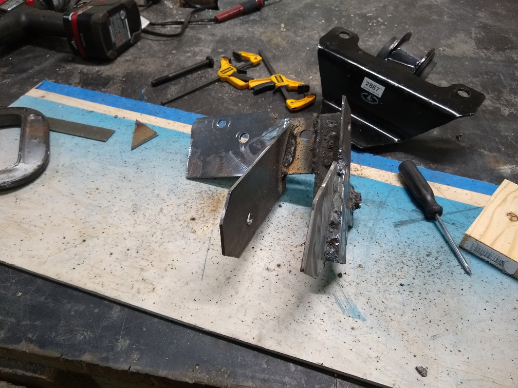
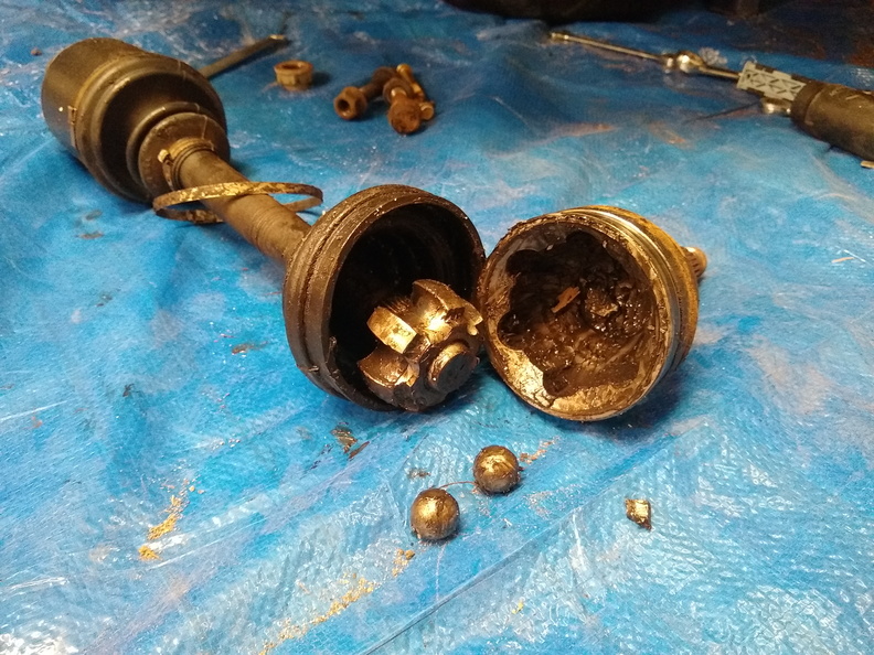
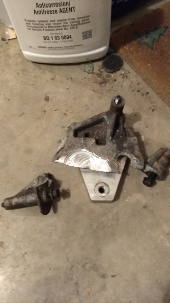
So, Nick fixed the axle up and sent it back. It was about $200 US plus the $45 to ship it up there. It looks nice and probably is all set to go.

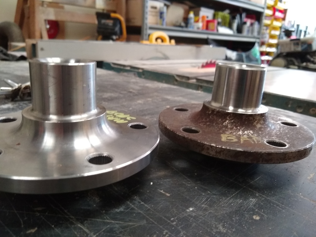
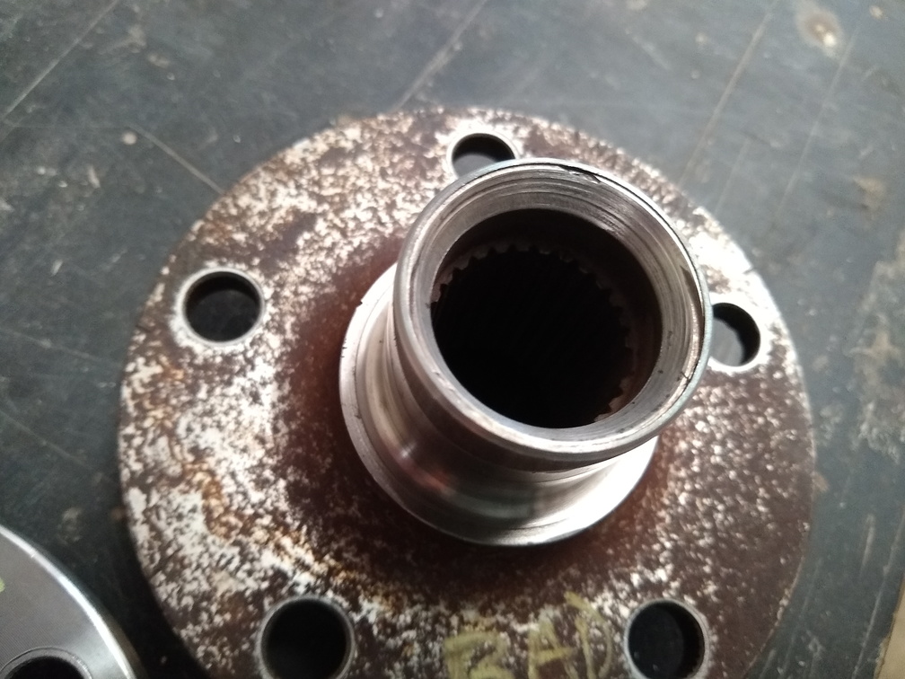
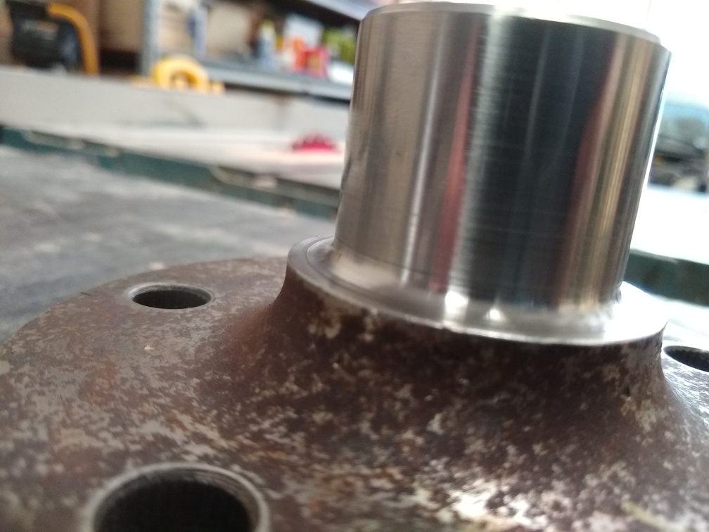
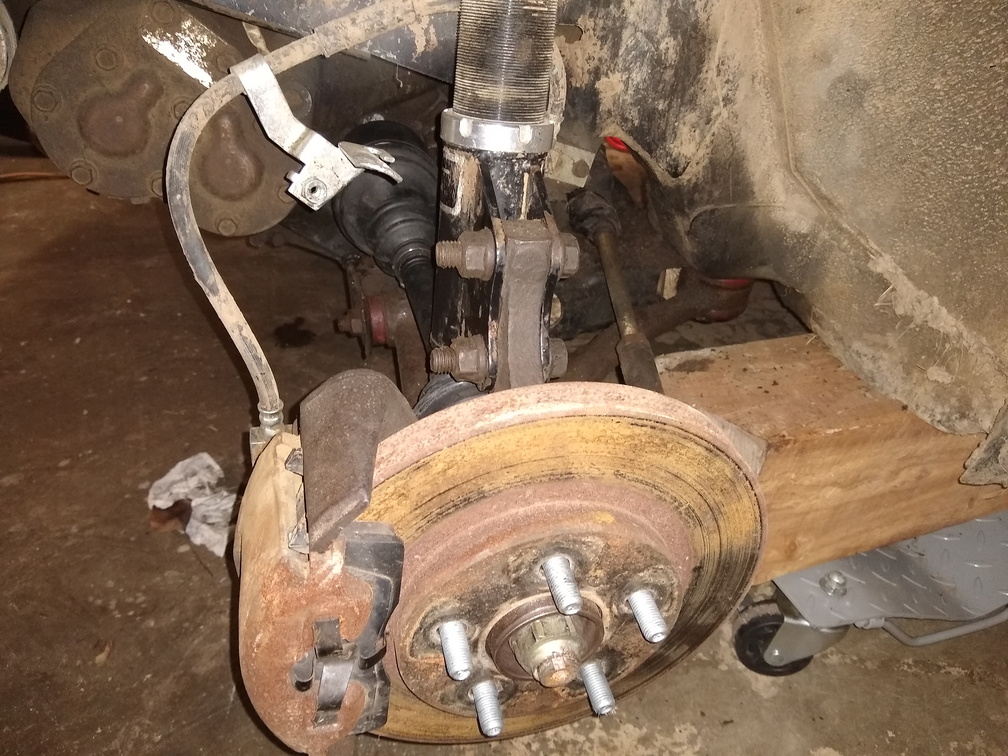
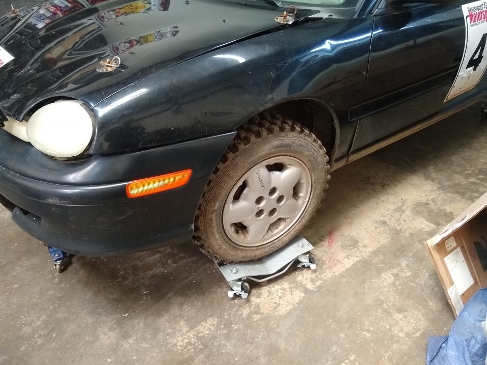
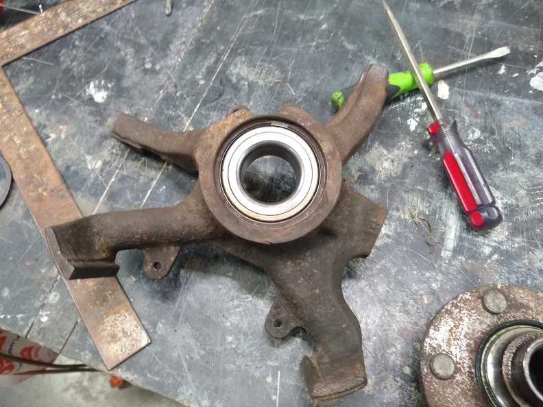
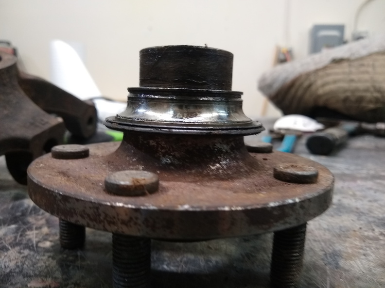
The next thing I discovered was that even after pressing in the new bearing, there was still some movement. Closer inspection revealed that the hub itself was loose inside the wheel bearing. I thought I was in luck, since Chris Greenhouse had given me a handful of hubs that A1CVTECH had made for him, but as it turns out, the stock hub is about 1/8″ too small for my axles, and his axles are about 1/4″ larger diameter than mine. So I have no easy way to replace my bad hub.

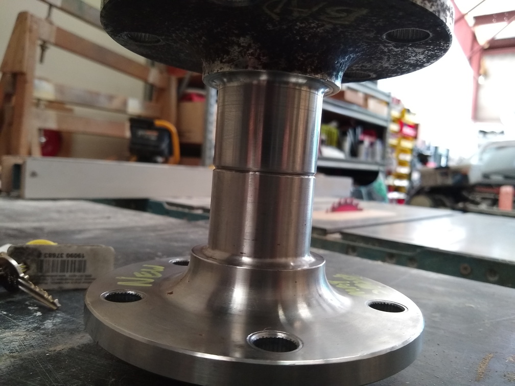
The first idea I had was to go ahead and ship a new hub to A1CVTECH and have Nick hog it out. But then I got to thinking about the cost involved with that – shipping alone! – and I went in search of a local place to do the work. I’ve got a line on a machinist who says he thinks he can do it, so I’ve ordered up a new Timken unit and as soon as it comes in, I’ll make an appointment with him to take it over along with the old one and see what he can do.

I really should update this more often

Everything seemed to be going pretty well until we got back to Bitzer’s on a regular basis and then it was motor mount shredding time. The mounts seem to be really solid and seem to work really well except on the surface there – and I attribute that to how extra-rough the land is. The lesson that I’m learning is that what works well on the street just isn’t enough for getting in the dirt!

At the last event of the 2019 season, I broke the motor mounts twice and also busted the CV joint. Despite having all winter to pull the car in and get it taken care of, I waited until March. As usual. Step one was getting this thing into the garage in the first place. I had it over on the side of the building so I had to use the truck to pull it out and then line it up as high up on the hill as I could to get it over the hump into the garage.

Lining up to pull the Neon from alongside the building
What could possibly go wrong with this?
The Neon inside the shop after a sometimes nerve-wracking pushme-pullyou adventure
Up on the casters for easier movement

With the car in the garage and up on the casters, I finally started to take a look. My original list at the end of the season for winter work was:

  • Send axle to be repaired by A1CVTECH
  • Figure out and build a front(ish) motor mount
  • Change oil
  • Maybe put the interior back in

Now that I was finally taking a good look at things, I found that not everything was as I expected. First of all, when the bobble strut went, it took the whole bracket with it:

It’s hard to see, but the blue bobble strut bracket is torn and bent up and to the left

I also discovered that the left wheel bearing was loose again. Not sure if that was a result of a bad bearing, the abuse of the field, whatever killed the CV joint, or a shoddy installation job. Or some combination.

As part of removing the axle, it helps to disconnect the sway bar from the control arm. I ran in to a problem with the endlink:

Somehow the end link bolt head went right through the hole at the end of the sway bar

This left me with a new and more expansive list:

  • Send axle to be repaired by A1CVTECH
  • Figure out and build a front(ish) motor mount
  • Change oil
  • Maybe put the interior back in
  • Replace the left wheel bearing
  • Replace the front sway bar end links
  • Fabricate a new bobble strut
  • Repair the bobble strut bracket

The motor mount conundrum is a little bit more complicated than just building a front motor mount. The engine needs some sort of additional bracing to prevent it from tipping forward. The two side mounts do a fine job of giving the engine a pivot point. The bobble strut provides stability in the rear of the engine. And the torque strut on the lower right side gives some stability. The engine still has plenty of ability to rock forward, though. The torque strut is pretty solid, but if the front of the engine wants to move down, it’s exerting all of that as shear force on a single bolt. I *think* that it’s a single-shear force and if that bolt was a grade 10.9 12mm bolt it would support about 3 tons of force before shearing. That means that in order to shear the bolt, the full weight of the motor would need to come forward onto that mount at about 6 inches per second. Which seems very possible.

That’s all probably very nit-pick-able and really loose, but I am not a structural engineer nor do I remember all that much from high school physics. But I suspect I’m on the right path.

So…. In order to prevent that from breaking, it would be much better to have some sort of support that the engine would come straight down on instead of relying on the shear strength of a single bolt. To that end, I am considering various possible solutions:

Run a section of box steel or angle iron from the core straight back to the K-member. Use some sort of body-mount style bushing to connect to the engine from the bottom.

Build a strut with rod end links and poly bushings to go up from the center of the core support to the bottom-front of the engine near where the starter is

Work around the structural collar to build some sort of plate that bolts to the engine and then to the regular 1gn Neon front mount position on the core support

I’m not sure which, if any of those, will be the winning decision, but I have started to photograph and measure the underside to try to get a better idea of how to go about it. I think that this bracket can be removed from the engine and either adapted or copied to provide a location to bolt on a front motor mount connection:

Slightly out of focus, the bracket that is in the center of this picture seems like the best candidate for a front motor mount attachment point

Moving on to other things, the axle is out and ready to be shipped back to Canada

I don’t know where the other 4 balls went, no do I know where the shard of metal came from

I also have the old wheel bearing pressed out and the new one pressed in

New wheel bearing pressed in

The hub still has the inner race from the old bearing attached. I need to get my puller out to the shop so I can remove it and press it into the new bearing to complete the hub and knuckle assembly.

Rock Auto is shipping me a new set of Energy Suspension end links for the sway bar as well as a new Timken wheel bearing so that I’ve got a spare on hand and ready to go. I’ve also ordered up a full set of brandy-new lug nuts since the cheap ones I have are hard to work with the aluminum wheels.

Two year update

Oh.  Hey there.  Has it really been two years since I made an update to this?  Wow.  Well, I guess there’s some catching up to do.

It was about April-ish of 2017 that I got a new suspension setup from AMR Engineering.  For about $1,700 I got 250lb springs in the rear and 200lb springs in the front on single-adjustable dampers with camber plates in the front.  So far, they’ve been working out really well.  On the street, the car is almost magical in its ability to hold corners and on the dirt, it performs amazingly, keeping the wheels on the ground and giving me a ton of grip.

They’re not that shiny any more, of course, but they’re working great.

Next up, I had to fiddle with the rear brakes a bit and those are all new and working well.  Although, the parking brake is still a little weak.  It’s on my list of things I need to look at.

I found that it was running a little warm so I built an aluminum shroud for the fans.  It looks pretty neat:

But don’t get too attached to it.  At first I was having problems with it getting really hot on the highway with the fans running.  Turns out, I wired them backwards.  Derp-a-doo.  With the fans turning the right way, things were okay.  But only just okay.  I could not hot-lap at an event without overheating the car.  I needed to run the cooling fans, the heat on full blast, and then spray the radiator with water between runs to keep it cooled down enough.  Back to that later.

Anyway, the next thing to break was yet-another-set of axles.  Killed the joint hard.  I made a bunch of calls and wound up paying about $900 for a pair of axles and new hubs/bearings from A1CVTech.  Nick promises me that I cannot break them and so far, so good.  These also have new hubs and wheel bearings so that he could use a thicker axle.  Funny story about that:  The axles came in the day before a Rallycross and Tim offered to help me put the wheel bearings in and all that for the new hubs.  But they forgot to send me my good expensive wheel bearings that came with the hubs I shipped them!  So, I wound up having to go scrounging parts stores for the stupid Chinese garbage.  One of them has already failed and I replaced it with the one of the good ones that A1CVTech shipped back to me.

Towards the end of 2017, however, disaster struck once again and the motor mount failed, severing the brake line.

I had a bit of a go-around with that, but finally got everything bolted up.  I think the core problem was this:

The bobble strut bracket had sheared off and I think that was allowing too much movement of the engine which was a significant contributing factor to the side mount breaking.  I haven’t had (too much) trouble with that since fixing this.

In early 2018, I did this:

Colleti did some tuning for me and got me from 180 horse at the wheels to 231hp and 324 ftlbs.  But, there’s more to that story.  When I got it home and off the trailer, I ran some errands with it.  When I got back, walking past the front left wheel I could feel immense heat coming from the car.  Turns out that the caliper was stuck so hard that I couldn’t turn the wheel by hand when it was up in the air.  So, those dyno numbers are with the brakes on.

I also got a new Mishimoto radiator and fans to install to help with the cooling issues.  Those finally went in recently and are working out.  Towards the end of the year,I had a major problem with the car running really lean and not wanting to restart.  Turns out that the positive cable on the alternator had ripped out.  I got a whole new alternator from Rock Auto, but it was bad out of the box, so another new one from FLAPS got it running again.  As long as the voltage reg connector stays in place, it runs great.

So far, I took 1st in MF at PE #2 and 3rd in MF in the Great Lakes Divisional.  Here’s hoping for a good season.